Nova Extrinsics Sensor Calibration Tool

Linux / arm64
Tool Overview
Deprecation notice: This NGC page and calibration tool is now deprecated. Please refer to the official Isaac site.
End-of-Life notice: The
release_3.2-aarch64tag of the container is still available for download, but is no longer actively maintained. It is compatible with JetPack 6.1 and Nova Orin Init 1.3.2.
The Nova Extrinsics Sensor Calibration Tool is a containerized application that provides extrinsic calibration between sensors on a Nova Carter robot or Nova Orin Developer Kit. On initial setup or when recalibration is required, this application is used to generate a URDF calibration file with the relative position of different sensors on the robot.
The URDF calibration file is used for robotics functions that combine information from multiple sensor modalities. This calibration process achieves highly consistent results by using calibration targets and a mobile device connected to the robot over a web browser, which guides you through the procedure of placing the calibration targets in different positions around the robot.
Visuals of the calibration tool guiding the operator to position a calibration target in different locations.
This tool is self-contained and performs both data collection and calibration optimization on the
robot. It does not require external services or an internet connection after the container is deployed
to the robot. By default the resulting URDF calibration file is deployed to /etc/nova/calibration/isaac_calibration.urdf.
If Isaac Cloud Services are available, this tool also provides automatic Over-The-Air (OTA) backup of calibration files, which can later be re-deployed using Isaac Cloud Services.
Requirements
The Nova Extrinsics Sensor Calibration Tool requires the following components and space considerations:
- Nova Carter robot or Nova Orin Developer Kit.
- Calibration targets (precisely printed following the description below).
- Mobile device (tablet recommended) attached to the back of the large calibration target.
- Access from the mobile device to the robot on the same Wi-Fi network.
- Bright room with diffuse light and open space around the robot and calibration target.
Calibration Targets
The Nova Extrinsics Sensor Calibration Tool uses two different checkerboards with the same pattern, each of them for different calibration tasks:
- Small checkerboard (PDF) for Camera-Ground calibration.
- Large checkerboard (PDF) for all the other calibration tasks and modalities.
Both of the PDF files, above, include the design of the checkerboards (page 1) and printing instructions (page 2) that must be followed for the tool to work properly.

Illustration of the checkerboard. Both the large and small checkerboards have the same pattern in different dimensions: 100mm squares vs 45mm squares respectively.
The checkerboards must have the following qualities:
- The material of the board must be a "Sandwich Composite" material with a low-density foam core and hard, laminated surfaces. "Ultraboard" is the recommended product for the calibration process, but any material adhering to the description provided would be sufficient.
- The checkerboard must be rigid without any noticeable bending when holding it during operation, or when flat on the ground.
- The dimensions of the checkerboard squares must be accurate, within +/- 1mm from nominal measurement. It is recommended that all new checkerboards have dimensions verified with a ruler or calipers for quality assurance.
Finding a Printing Service
There are different ways to find a service to print calibration targets, for example:
- Contacting printing services in your area and providing the specifications outlined above.
- Searching with a preferred search engine, for example: "ultra board" 3/4 inch printing <your area>.
- Finding local foam board suppliers for Ultraboard.
Mobile Device
The calibration tool runs on the robot but requires that the operator use a mobile device (tablet recommended) attached to the back of the large calibration target for visualization of the tool's web UI. Otherwise, images might look flipped.
- Device specs: 10.5'' screen or larger and a case to attach to
the large calibration target.
- Tablet example: Galaxy Tab A8 (SM-X200)
- Web browser: Google Chrome at the latest version available in the app store.
- Wi-Fi requirements: Mobile device needs to be on the same Wi-Fi as the robot being calibrated. Wi-Fi connection needs to be stable and strong.
Hand Holders and Mobile Device Case
It is necessary to attach three holders at the back of the large calibration target, one for each hand and one for the mobile device (tablet case is sufficient).
Use strong velcro (able to hold 15 lb or more) to attach the mobile device and the holders at the back of the large calibration target, as shown in the image below.
NOTE: Do not hold the large calibration board by its sides. Any occlusion or modification of the checkerboard borders may lead to a non-optimal or invalid calibration result.
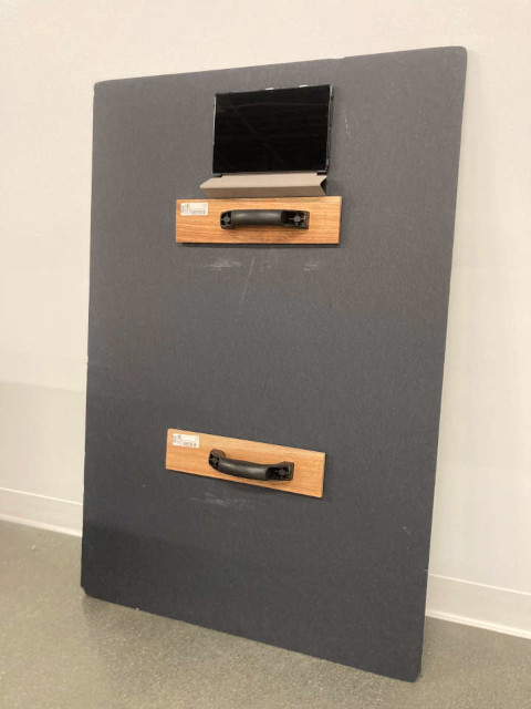
View of the back of the large checkerboard with tablet and holders attached with velcro.
Space Requirements
Illumination
You must perform the calibration process in a bright room with diffuse light, to avoid glare on the calibration target.
Open Space Around the Robot and the Calibration Targets
During the full calibration process the robot must be on flat ground. 4 m - 6 m of empty space around the robot and 2 m of empty space around the large calibration board are required at all times. Space requirements are per camera.
During the calibration process, you must:
- Hold the large calibration target by the handles on its back.
- Keep the large calibration target away from walls, objects, and body parts at all times.
- Avoid people and dynamic objects between the robot and the calibration board.
- Make sure that the front of the calibration target is not obscured in any way, no matter how small.
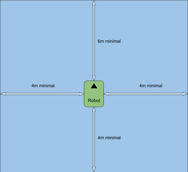
Empty space requirement around the robot: 4 m in each direction and 6 m in the direction of the camera currently being calibrated.
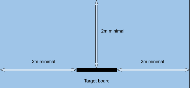
Empty space requirement around the large target board during calibration: 2 m in each direction.
If the app guides you to poses that are close to objects or unreachable, feel free to reposition the robot, wait for the robot to be static in the new position and keep following the steps in the UI. Do not move the robot while following the steps on the UI.
Calibrating a Robot
The calibration process uses a web-based app running on a Nova Carter robot or Nova Orin Developer Kit, a calibration target, and a mobile device. Make sure you have all the components before starting the calibration process.
The web-based app supports the calibration of the following tasks:
FOUR_FISHEYES: Front fisheye camera - left fisheye camera - right fisheye camera - rear fisheye camera (Nova Carter only)FISHEYES_FRONT_LEFT_RIGHT: Front fisheye camera - left fisheye camera - right fisheye cameraSTEREO_FISHEYE_FRONT: Front stereo camera - front fisheye cameraSTEREO_FISHEYE_REAR: Rear fisheye camera - rear stereo camera (Nova Carter only)STEREO_FISHEYE_LEFT: Left fisheye camera - left stereo cameraSTEREO_FISHEYE_RIGHT: Right fisheye camera - right stereo cameraGROUND --ground-sensor front_stereo_camera: Robot/ground - Front stereo cameraGROUND --ground-sensor front_3d_lidar: Robot/ground - 3D LidarFRONT_STEREO_LIDAR: 3D Lidar - front stereo cameraFRONT_REAR_STEREO_LIDAR: 3D Lidar - front stereo camera - rear stereo camera (Nova Carter only)LEFT_RIGHT_STEREO_LIDAR: 3D Lidar - left stereo camera - right stereo camera (Nova Carter only)
The calibration process involves the setup of the environment and calibration steps following the instructions in the web app.
Deploying the Container and Preparing the Environment
End-of-Life notice: The
release_3.2-aarch64tag of the container is **compatible with ** JetPack 6.1 and Nova Orin Init 1.3.2.
Set up the robot by following the Nova Carter getting started guide or Nova Orin Developer Kit getting started guide. This step installs Nova Orin Init and sets up Docker. Nova Orin Init configures the robot and deploys the CAD nominals file in
/etc/nova/calibration/isaac_nominals.urdf. Verify that Jetpack version is 6.1 and Nova Orin Init version is 1.3.2.Open a terminal, ssh to the robot and pull the Docker image (one-time setup):
ssh nvidia@<robot_ip>
docker pull nvcr.io/nvidia/isaac/nova_extrinsics_sensor_calibration_tool:release_3.2-aarch64
- Create a file named
run_calibration_app.shin the robot and add the following content (one-time setup):
#!/bin/bash
IMAGE_PATH=nvcr.io/nvidia/isaac/nova_extrinsics_sensor_calibration_tool:release_3.2-aarch64

docker run -it --rm --privileged  --network=host \
        --entrypoint /usr/bin/python3 \
        --mount type=bind,source=/dev,target=/dev  \
        --mount type=bind,source=/etc/nova,target=/etc/nova \
        --mount type=bind,source=/sys/devices,target=/sys/devices  \
        --mount type=bind,source=/tmp/argus_socket,target=/tmp/argus_socket  \
        --mount type=bind,source=/sys/bus/iio/devices,target=/sys/bus/iio/devices \
        --mount type=bind,source=/mnt/nova_ssd/recordings,target=/mnt/nova_ssd/recordings  \
        $IMAGE_PATH /app/extensions/calibration/apps/calibration_app "$@"
- (Nova Carter only) If planning to use Lidar for calibration, set the Hesai Lidar to
FIRSTreturn mode by running the command below. This setting allows the calibration software to receive the Lidar pulses corresponding to the calibration target instead of their potential reflections.
/opt/nvidia/nova/python/venv/bin/python3 -c '
from nova_init.hesai.hesai_utils import *
l = HesaiLidar("192.168.1.201")
print(f"Previous setting: {l.get_return_mode()}")
l.set_return_mode(HesaiReturnMode.FIRST)
if l.get_return_mode() == HesaiReturnMode.FIRST:
    print("SUCCESS. Lidar set to FIRST return mode")'
NOTE: This is a persistent change, make sure to set it back to its default setting (for example,
FIRST_STRONGEST) after calibrating the robot.
NOTE: Not performing this step may lead to slowdowns in the calibration app and inaccurate results.
- Uncover cameras and LIDAR (if present) from obstructions, such as removable covers and protective stickers on camera lenses.
Calibrating Nova Carter Sensors
The following sequence of steps describes the process to calibrate all the sensors in Nova Carter, using the front stereo camera to calibrate with the ground (also known as the anchor sensor in the remainder of this document):
Front stereo camera to ground and front stereo camera to 3D Lidar:
Place the small calibration target flat on the ground. Make sure that the large checkerboard is not in sight of the camera stream when performing the camera-to-ground step. Make sure the small calibration target is close enough to the camera for detection. Try to position the board such that it's as close as possible to the camera without it being occluded or partially out of the camera frame.
After the ground plane is estimated, the tool switches to Lidar-camera calibration mode. Then, it guides the operator to place the large checkerboard in different locations in the scene to calibrate the Lidar with respect to the front stereo camera.
Front stereo camera to front fisheye camera: From this step onwards, the tool uses camera-camera calibration to estimate the remaining transformations between sensors.
Front fisheye camera to left, right, and rear fisheye cameras.
Rear fisheye camera to rear stereo camera.
Left fisheye camera to left stereo camera.
Right fisheye camera to right stereo camera.
After following the previous steps, the hierarchy of calibrations between sensors is described by the following transformation tree:
Robot
│
Front Stereo Camera
   │
   ├─ Lidar
   │
   └─ Front Fisheye Camera
      │
      ├─ Rear Fisheye Camera
      │  └─ Rear Stereo Camera
      │
      ├─ Left Fisheye Camera
      │  └─ Left Stereo Camera
      │
      └─ Right Fisheye Camera
         └─ Right Stereo Camera
NOTE: You can perform the following calibration without a 3D Lidar. Skip the first step and make sure to perform the ground calibration (
--ground-sensor) in the second step along with front stereo - front fisheye camera calibration. To just perform the ground calibration and nothing else, you can choose the--calibration-type GROUNDand specify the--ground-sensor.
Verify that the robot is on flat ground and with the required empty space around it.
Open a terminal, ssh to the robot, and run the commands below step by step. After launching every command follow the instructions from step 3 onwards until calibration succeeds. Then return to this step to launch the following commands:
a. Front stereo camera - 3D Lidar step with ground calibration with respect to front stereo camera (anchor). This step is optional (depending if the 3D Lidar is present and needs to be calibrated):
bash run_calibration_app.sh --calibration-type FRONT_STEREO_LIDAR --ground-sensor front_stereo_cameraNOTE: The app asks the operator to put the board on the floor near the robot, use the small board that does not have handles on the back so that board is flush with the ground. If the board is not detected, then move it around and close to the robot to perform the ground calibration step.
b. Front stereo camera (anchor) - front fisheye camera. This step has two options, depending whether the operator executed the first step or not:
- If the first step was executed:
bash run_calibration_app.sh --calibration-type STEREO_FISHEYE_FRONT- Alternatively if the first step was not performed (for example, because 3D Lidar is not in the
system), make sure to add the
--ground-sensor front_stereo_cameraflag.
bash run_calibration_app.sh --calibration-type STEREO_FISHEYE_FRONT --ground-sensor front_stereo_camerac. Front fisheye camera (anchor) - rear fisheye camera - left fisheye - right fisheye step:
bash run_calibration_app.sh --calibration-type FOUR_FISHEYESd. Right stereo camera - right fisheye camera (anchor):
bash run_calibration_app.sh --calibration-type STEREO_FISHEYE_RIGHTe. Left stereo camera - left fisheye camera (anchor):
bash run_calibration_app.sh --calibration-type STEREO_FISHEYE_LEFTf. Rear stereo camera - rear fisheye camera step (anchor):
bash run_calibration_app.sh --calibration-type STEREO_FISHEYE_REAROpen Google Chrome in the mobile device behind the large calibration board and navigate to the following address:
http://<robot_ip>:3000/calibration.html
If any calibration step fails, you are prompted to re-launch the calibration app (rerun the same command to launch the app again).
- Follow the instructions in the mobile device and place the checkerboard in the requested positions by aligning the contour of the red dots with the blue rectangle (dots). For example:
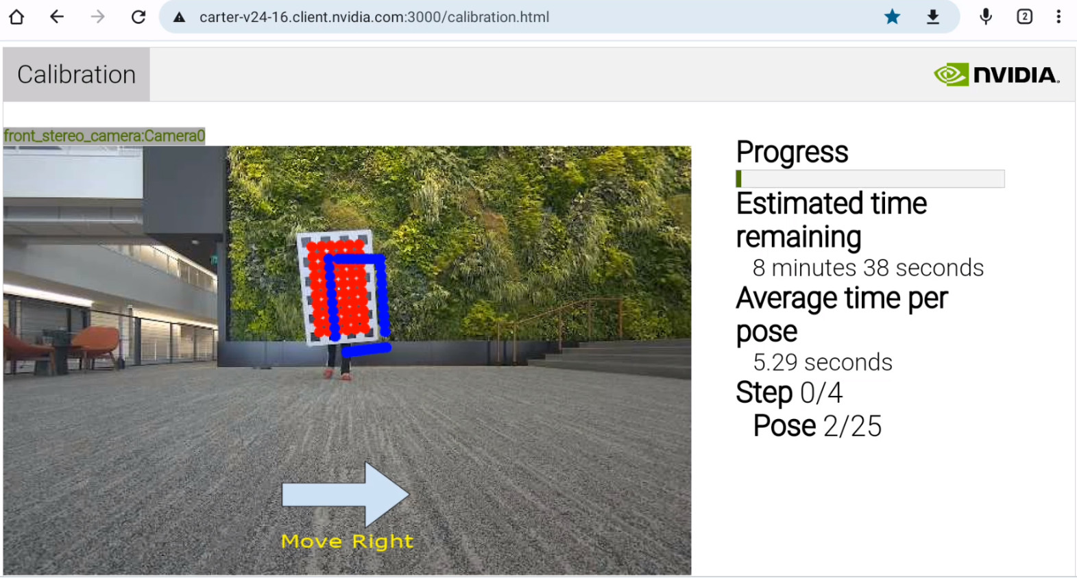
Screenshot of the calibration tool web UI guiding the operator to position the checkerboard towards their right.
You must:
- Hold the calibration target by the handles in its back. It must not be held by its sides.
- Keep the calibration target away from walls, objects, and body parts at all times.
Operator correctly rotating the calibration target guided by the calibration tool.
Calibrating Nova Orin Developer Kit Sensors
The following sequence of steps describes the process to calibrate all the sensors in Nova Orin Developer Kit, using the front stereo camera to calibrate with the ground (also known as the anchor sensor):
Place the Nova Orin Developer Kit on a flat surface around 30 cm (12 inches) from the ground
Camera-camera calibration for all cameras in Nova Orin Developer Kit: The web tool guides the operator to place the large checkerboard in different locations in the scene, for each of the following calibration tasks. Open a terminal, ssh to the robot, and run the commands below step by step. After launching every command follow the instructions from steps 3 and 4 from Calibrating Nova Carter Sensors until calibration succeeds. Then return to this step to launch the following command:
- Front stereo camera to front fisheye camera:
bash run_calibration_app.sh --calibration-type STEREO_FISHEYE_FRONT- Front fisheye camera to left and right fisheye cameras.
bash run_calibration_app.sh --calibration-type FISHEYES_FRONT_LEFT_RIGHT- Left fisheye camera to left stereo camera.
bash run_calibration_app.sh --calibration-type STEREO_FISHEYE_LEFT- Right fisheye camera to right stereo camera.
bash run_calibration_app.sh --calibration-type STEREO_FISHEYE_RIGHTAssemble the Nova Orin Developer Kit on the robot such that the camera’s field of views are unobstructed and the small calibration target is fully visible when placed close to the robot and flat on the ground. Make sure to orient the Nova Orin Developer Kit such that the front camera is pointing to the robot’s main direction of travel, and the bottom plate is parallel to the ground.
Front stereo camera to ground calibration: Follow the instructions in the Calibrating Camera to Ground Section with one important difference: Instead of creating a new URDF file, edit the file
/etc/nova/calibration/isaac_calibration.urdf(orisaac_nominals.urdfif calibration file is not present). In particular, edit the line:<origin xyz="-0.016000 0.075000 0.012500" rpy="0.000000 0.000000 0.000000"/>In the code block:
<joint name="front_stereo_camera_joint" type="fixed">
    <origin xyz="-0.016000 0.075000 0.012500" rpy="0.000000 0.000000 0.000000"/>
    <parent link="base_link"/>
    <child link="front_stereo_camera"/>
</joint>
For example, if you are mounting the Nova Orin Developer Kit such that its center-front point is at a height of Z = 0.4 m above the robot origin and X = -0.1 m behind it, the
front_stereo_camerajoint should be adjusted accordingly to reflect Z = 0.4123 m above the robot origin, X = -0.116 m behind it, and Y = 0.075 to its left:<joint name="front_stereo_camera_joint" type="fixed"> <origin xyz="-0.116000 0.075000 0.412500" rpy="0.000000 0.000000 0.000000"/> <parent link="base_link"/> <child link="front_stereo_camera"/> </joint>
After following the previous steps, the hierarchy of calibrations between sensors is described by the following transformation tree:
Robot
│
Front Stereo Camera
   │
   └─ Front Fisheye Camera
      │
      ├─ Left Fisheye Camera
      │  └─ Left Stereo Camera
      │
      └─ Right Fisheye Camera
         └─ Right Stereo Camera
Calibrating Camera to Ground in Custom Configurations of Nova Sensors
This section describes the camera-robot/ground calibration process, and it is not limited to
Nova Carter or Nova Orin Developer Kit. It supports custom locations of the
front_stereo_camera, and it has
been tested with elevations (Z) ranging between 0.15 m and 0.75 m with camera parallel to the
ground.
NOTE: The calibration target on the ground needs to be visible by the
front_stereo_cameraat a close distance to the robot. The exact distance depends on camera position and orientation.
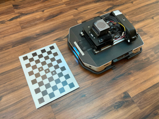
View of the Camera-robot/ground calibration step, showing the small calibration target flat on the ground, in front of a robot with a Nova Orin Developer Kit.
Camera-robot/ground calibration involves the following steps after mounting the sensors on the robot:
- Measure the position and orientation of the front stereo camera
(
front_stereo_camera) with respect ofbase_linkin CAD model of your robot or with measuring tape. Note that the origin of thefront_stereo_camerais in its left principal point, andbase_linkis on the ground. - Create a robot URDF with the transformation measured in the previous step, and place it the
following path in the robot
/etc/nova/calibration/isaac_nominals.urdf. For example, in the particular case of a robot with only onefront_stereo_camera(isaac_nominals_single_camera.urdf), edit the line:
<origin xyz="0.000000 0.000000 0.000000" rpy="0.000000 0.000000 0.000000"/>
In the code block:
<joint name="front_stereo_camera_joint" type="fixed">
    <origin xyz="0.000000 0.000000 0.000000" rpy="0.000000 0.000000 0.000000"/>
    <parent link="base_link"/>
    <child link="front_stereo_camera"/>
</joint>
For example, if you are mounting the front_stereo_camera such that its principal point at a height
of Z = 0.4 m above the robot origin and X = -0.1 m behind it, the front_stereo_camera joint should
be adjusted accordingly:
<joint name="front_stereo_camera_joint" type="fixed">
    <origin xyz="-0.100000 0.000000 0.400000" rpy="0.000000 0.000000 0.000000"/>
    <parent link="base_link"/>
    <child link="front_stereo_camera"/>
</joint>
- Verify that the robot is on flat ground and with the required empty space around it.
- Place the small calibration target flat on the ground. Make sure that the large checkerboard is not in sight of the camera stream when performing the camera-to-ground step. Make sure the small calibration target is close enough to the camera for detection. Try to position the board such that it is as close as possible to the camera without it being occluded or partially out of the camera frame.
- Open a terminal, ssh to the robot, and execute the ground calibration command:
bash run_calibration_app.sh --calibration-type GROUND --ground-sensor front_stereo_camera
- Open Google Chrome in your preferred device, navigate to
http://<robot_ip>:3000/calibration.html, and click the button in the web UI to perform ground calibration. If the board is not detected, adjust the position of the calibration target accordingly following the previous instructions.
Calibration File Usage and Backup
- The outcome of the calibration process is a URDF calibration file:
/etc/nova/calibration/isaac_calibration.urdf. - By default isaac-ros applications expect the URDF calibration file to be located in the path defined above.
- It is recommended to backup the calibration files.
- If Isaac Cloud Services are available, refer to the following section for automatic backup.
OTA Backup and Update
Calibration file OTA backup and deploy is available to users of Isaac Cloud Services. See the OTA File Service page for documentation and deployment instructions.
After the (OTA service is configured),
calibration files are automatically backed up at the end of the calibration execution, if the
calibration app is launched with the following additional command-line argument:
--upload-bucket <bucket_name>
NOTE:
bucket_namemust be the name you give when creating your bucket.
Performance
Repeatability
The repeatability error is measured as the transformation between a given sensor calibration and the mean transformation from a set of repeated calibrations for the same sensor.
For stereo Camera-Lidar calibration, rotation is expected to be under 2.7 mrad and translation under 1.5 cm of repeatability error.
For Camera-Camera calibration, rotation is expected to be under 1.0 mrad and translation under 0.7 cm of repeatability error.
For Camera-Ground calibration, rotation is expected to be under 3.4 mrad and translation under 0.7 cm of repeatability error.
Re-projection Error
The re-projection error is measured as the pixel distance between estimated keypoints and detected keypoints for each pair of cameras with overlapping field of view. The re-projection of 99% of keypoints is expected to be under 1.1 pixels.
Time Duration
Extrinsic calibration of all available sensors is expected to take approximately 30 minutes on Nova Carter and 15 minutes on Nova Orin Developer Kit.
Data collection and calibration time varies per each sensor modality, approximately taking:
- Camera-Camera: 2 minutes (for each camera pair).
- Camera-Ground: 1 minute or less (only performed once).
- Lidar-Camera: 10-15 minutes (typically only performed once if Lidar is available).
Limitations
Application Designed for Nova Carter and Nova Orin Developer Kit
The extrinsic calibration tool is designed specifically for the Nova Carter robot, Nova Orin Developer Kit, and their sensors (3D Lidar and cameras). Different robots and sensor configurations are not supported at the moment.
Extrinsic Recalibration Required after Recalibration of Stereo Cameras
It is necessary to recalibrate the robot extrinsics (i.e. by running the tool described in this page) if the calibration of any stereo camera in the platform changes (i.e. by overwriting the values in the EEPROM).
Sensor Modalities and Usability
The calibration tool performs Lidar-robot/ground calibration, camera-robot/ground calibration, Lidar-stereo camera calibration, and camera-camera calibration for all fisheye and stereo cameras in Nova Carter. Lidar-robot/ground and camera-robot/ground calibration refer to estimating the relative pose of the sensor (3D Lidar or camera) with respect to the ground and includes 3 degrees of freedom: pitch, roll, and translation in Z axis.
The calibration takes multiple incremental steps to calibrate all the desired sensors in the robot, where each of the steps includes a subset of sensors. The URDF calibration file is modified with each calibration step and its content is used in remaining calibration tasks. See the Calibrating Nova Carter Sensors section for details on the specific calibration steps.
Steps may involve calibration of multiple sensors (sub-steps). If any calibration sub-step fails (for example, Lidar-front stereo camera), the operator is directed to restart the calibration process from the beginning of that step. Nominals are provided for the remaining sensors.
Space and Calibration Target
Follow the instructions for space and calibration target requirements to minimize the failure rate of the tool.
Versions
- 2.1.0 Supporting Lidar-robot/ground calibration, and Lidar-camera calibration for the 4 stereo cameras and 3D Lidar on Nova Carter.
- 3.0.0 Supporting the following calibration modalities: Lidar-robot/ground, Lidar-stereo camera, camera-robot/ground, and camera-camera calibration for all cameras and 3D Lidar sensors on Nova Carter. JSON calibration file is deprecated. This version transitions to URDF for both calibration output and input of CAD nominals. This version also supports OTA backup of calibration files for Isaac Cloud Service users.
- 3.0.1 Supporting Nova Orin Developer Kit. Supporting camera-ground for
front_stereo_camerain custom configurations of Nova Sensors. Camera-ground calibration improves low-lying object perception for Isaac Perceptor. - 3.2 Supporting JetPack 6.1. Added deprecation notice.
License
Nvidia Isaac ROS Software License.